
Automatic Relay Protection Tester (Three Phase)
General Information:
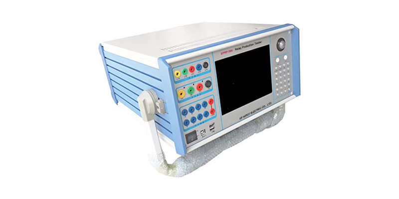
Protection systems play a key role for the safe and reliable operation of today’s electricity power systems. Properly working protection devices help to maintain the safety of the system and to safeguard assets from damage. EPRP-404 Relay Protection Tester is the essential test tool for relay protection technicians.
Main Features:
-High-Performance Industrial Control Computer
High performance Industrial control computer is adopted as the controlling computer, through which you can run the windows operating system directly. 8.5"TFT true color LCD display, tracking ball and optimized keyboard are located on the faceplate of this tester, which can be used without the external mouse and keyboard. USB interface, 10-100M net mouth and serial communication interface are located on the back plate of this tester, through which you can access data, communicate data and upgrade software conveniently.
The whole process and the result of the test will all be showed on the LCD. The Chinese operational interface of the complete set is very friendly and convenient. The tracking ball and keyboard on the faceplate will implement the operation. The operation is simple and convenient, and is easy to be mastered. Operator only needs a little knowledge of computer.
Keyboard and mouse interface are also located on the faceplate. If you would like to use the external mouse and keyboard, through pluging them with corresponding interfaces, you can operate this tester just like operating a desk-top computer.
-Digital Signal Processor Micro
High-speed digital controlling processor is adopted as the output core of the tester. 32 bit double precision arithmetic is employed in the software, through which arbitrary high-accuracy waveforms of each phase can be produced. Since integrative structure is adopted, the structure of the tester is layed compactly.The distance of data transmission is short with tight structure, which overcomes the problem of fewer points of waveform output due to long data communicational line and narrow frequency band when using the test controller controlled directly by PC.
-D/A Conversion and Low-Pass Filtering
High precision D/A converter is employed for ensuring the precision and linearity of current and voltage in the whole range.
Due to high density of fitting ponit, fidelity of waveform is high and harmonic component is small, which doesn’t have a strict requirement on the low-pass filter. Consequently, it has good characteristics of transient, phase frequency and amplitude frequency, which is easy to perform accurate phase-shifting and harmonic superposition and ensures very high precision even when the frequency is high.
-Voltage and Current Amplifier
For phase current and voltage, we persist in adopting high performance linear amplifier output mode in order to make the current and voltage source to directly output all kinds of waveforms from the DC waveform to the waveforms including all kinds of frequency components, such as square wave, combined waveform overlapped by each order harmonic, fault transient waveform, etc. In addition, the output waveform is clear and smooth without high-frequency radiated interference with neighboring equipment. It can simulate well all kinds of current and voltage characteristics under the circumstance of short circuit fault.
For power amplifier circuit, we adopt import power parts with high-power and hi-fi module style as power output, combining with heat dissipation structure laid elaborately and reasonably, it has enough large power redundancy and thermal capacity. The power amplifier circuit has overheated, overflow, overvoltage, and short circuit protections. When overflow occurs in the current circuit and overload or short circuit occurs in the voltage circuit, it will limit the output power automatically, switch off the whole power amplifier circuit and give alarm signal. In order to prevent the overheat of the power amplifier for long time operating under large current, a software time terminating system under large current is set in this tester. It can work for a long period when outputting is 10A or below. When the current is over 10A, the tester will start up the software time termination order. When time is up, the software will forbid power output automatically and give alarm signal. The higher output current is, the shorter the limiting time will be.
-Digital Input and output
This tester has 7 channels digital input and 4 pairs output.
The switching input circuit is compatible for both the empty contacts and 0-250V electric potential contacts in the input and output circuit. When the electric potential contacts are selected, 0-6V belongs to closed switch and 11-250V belongs to open switch. The switching capacity can test the action time and the action time interval of every phase switch’s contact conveniently.
The part of the digital input is isolated from the resources of the mainframe and the amplifier. The end of the digital input is hung, so the common end of the digital input is separated from the Common End UN, IN of current and voltage parts.
Switching potential input has directivity, you should connect the common end with the positive terminal of potential, and connecting the input end with negative terminal of potential for ensuring the potential of common end is higher than the one of input end. In practice, you should connect the input common end with +KM, and connect the negative terminal of contact with input end. Or,you can’t test it correctly.
The output part is the free contact output of relay. Output capacity is DC:220V/0.2A,AC:220V/0.5A. Output of switching capacity is independent of voltage, current, input and all other parts. Action process of each digital output part is different in each testing module. For details, please refer to the operation instruction on software module.
-Auxiliary DC Power Supply Output for Special Use
A circuit of special adjustable DC power supply output is located on the rear panel, which has 110V and 220V two shifts that can be used as test standby power supply on the spot. Rated current of this power supply is 1.5A, which can be used as DC power supply of protective tester or switch loop supply. If overload or short circuit occurs, corresponding protector tube will be burned out (2A/250V), you will only need to change this protector tube at that time.
Technical Specifications:
| AC current output | |
| Phase current output (effective value) | 0~40A |
| Output Precision | |
| 3 phase parallel current output (effective value) | 0~120A |
| A Long-time Phase current | 10A |
| Maximum output power of Phase current | 420VA |
| Maximum output power of 3 parallel current | 900VA |
| Maximum Permitted work time of 3 parallel current | 10S |
| Frequency range ( fundamental) | 20~1000Hz |
| Harmonic time | 1~20 times |
| DC current output | |
| Current output | 0~±10A / phase, 0~±30A / 3 parallel |
| Output Precision | |
| AC voltage output | |
| Phase voltage output (effective value) | 0~120V |
| Output Precision | < 0.2 degree |
| Line voltage output (effective value) | 0~240V |
| Phase voltage / Line phase output power | 80VA / 100VA |
| Frequency range (fundamental) | 20~1000Hz |
| Harmonic time | 1~20 times |
| DC voltage output | |
| Phase voltage output range | 0~±160V |
| Output Precision: | |
| Line voltage output range | 0~±320V |
| Phase voltage / Line phase output power | 70VA / 140VA |
| Binary & Time measuring | |
| Binary input | 7 channels |
| Idle contacts | 1~20mA,24V |
| Potential contact access | "0": 0 ~ + 6V; "1": +11 V ~ + 250V |
| Binary output | 4 Paris DC:220V/0.2A;AC:220V/0.5A |
| Time measuring range | 0.1ms~9999s |
| Measuring accuracy | <0.1mS |
| Power Source | AC 220V±10%,50/60Hz |
| Environmental temperature | -10℃~+50℃ |
| Dimension | 400×360×160mm³ |
| Weight | 18kg |